
Product
-
Weather station
-
Road Weather Station
-
Photovoltaic Inspection
-
Atmospheric monitoring
-
Operating condition monitoring
Recommended article
- The price of meteorological monitoring systems varies from 3,900 to 39,800 yuan depending on the number of monitored elements
- Power Quality Measurement Makes Power Grid Harmonic Detection and Data Logging More Efficient
- High-Precision Meteorological observation equipment Aids Field Environmental Monitoring
- How Forest Weather Station Improves Forest Fire Risk Early Warning Capabilities Through Real-Time Data Acquisition
- The Electrical Power Analyzer's four-channel synchronous measurement capability enhances the efficiency of photovoltaic grid-connected testing
- How Ultrasonic Snow Depth Monitoring Stations Achieve Accurate Snow Depth Measurement
Contact us
Shandong Fengtu IOT Technology Co., Ltd
Sales Manager:Ms. Emily Wang
Cel,Whatsapp,Wechat:+86 15898932201
Email:info@fengtutec.com
Add:No. 155 Optoelectronic Industry Accelerator, Gaoxin District, Weifang, Shandong, China
Road Weather Sensors
Model:FT-N20
Brand:fengtu
 Get a Free Quote
Related products
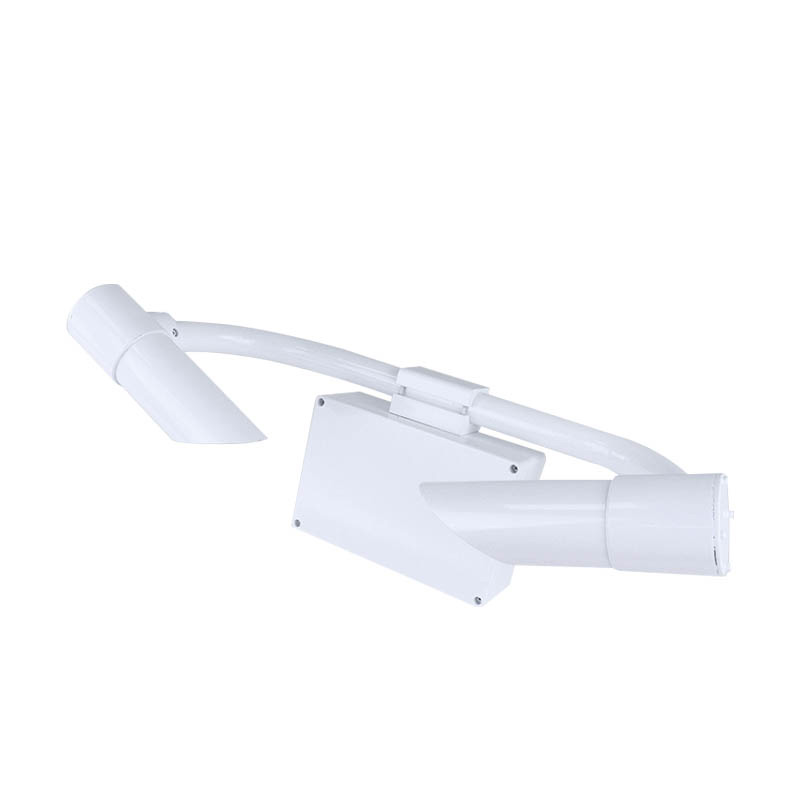
1. Road Weather Sensors Product Introduction
Road Weather Sensors are non-contact road condition sensors designed for road weather information systems that provide data such as road visibility.N20 Road Weather Sensors use the forward scattering method to measure the total extinction coefficient of the air and then calculate the current visibility. They are widely used in road transportation, meteorology and other industries.
2. Technical features of Road Weather Sensors
1. The instrument shell is made of high-quality aluminum material, which is spray-painted after anodizing. The whole machine has excellent waterproof, dustproof and anti-collision properties;
2. The transmitting and receiving lenses of the instrument are designed downward, which greatly reduces interference from stray light such as sunlight;
3. Weather phenomenon recognition, which can identify fog, rain, snow, mixed precipitation, sunny and other weather phenomena, with a high recognition rate;
4. Built-in watchdog circuit to ensure reliable and stable outdoor operation for a long time;
5. The instrument communication and power interfaces all include lightning protection designs, which greatly reduce lightning strikes and static electricity damage;
6.12~24V wide voltage power supply, total power is about 1W, very low power consumption, and can be powered by solar panels, batteries, etc. for a long time;
7. The digital interface uses RS485 or RS232, standard MODBUS protocol, no protocol adaptation is required;
8. The instrument can output 15s, 1min, and 10min visibility values, which can be read directly without configuration, making it more flexible to use.
3. Road Weather Sensors implementation standards
QX/T 536-2020 Forward scattering visibility meter test method
4. Technical indicators of Road Weather Sensors
| Main parameters | Parameter range | resolution | error |
| Measuring range | 20km | 1m | ≤2km ±2%2km~10km ±5%>10km ±10% |
| Repeatability | ≤4% | ||
| weather phenomena | Fog, rain, snow, mixed precipitation, sunny | ||
| Weather phenomenon recognition rate | ≥95% | ||
| working temperature | -40~60℃ | ||
| Working humidity | 0~100%RH | ||
| Working power supply | 12~24V | ||
| Power consumption | 1W | ||
| size | 610x230x360mm (length x width x height) | ||
| weight | ≤10kg | ||
5. Road Weather Sensors installation instructions
1. Installation location
The installation location of the visibility meter needs to be on an open, flat, unobstructed ground, away from buildings, trees, shrubs, peaks and other objects. This ensures that the instrument's observation range is not blocked and the data is more accurate.
Unnecessary optical interference should be avoided. The receiver of the visibility meter should be installed facing away from a strong light source (such as sunlight), and the transmitter and receiver should be located in the north-south direction.
2. Installation height
The installation height of the visibility meter should be greater than 1.5m and less than 3m. If the installation height exceeds 3m, the corresponding height should be calibrated.
3. Installation steps
3.1 Before installation, the user should prepare the upright column and install it on the upright column using the clamp provided with the instrument.
3.2 Lift the instrument to a suitable position and use the bolts behind the clamp to install and fix the visibility meter. During installation, ensure that the openings of the receiver and transmitter are facing downwards, otherwise they should be reinstalled.
Related article
-
Compact weather station with a variety of functions
2024-07-11 -
Ground Penetrating Radar: Non-Destructive Inspection for Urban Road Health Assessment
2025-06-30 -
Forestry Weather Station: Your All-in-One Fire Risk Sentinel in the Woods
2024-12-09 -
Weather Instruments: Navigating Farms Through the Complexities of Climate for Bumper Crops
2025-02-18 -
Application of the Series power supply 1500V High-Voltage Output in EL Testing
2026-07-15 -
Fengtu's Photovoltaic Module Dust Monitoring System: Ensuring Solar Efficiency through Precision Technology
2024-10-28 -
Detecting Deep - Buried Non - Metallic Pipelines with Ground Penetrating Radar
2025-03-05 -
Mechanical and Ultrasonic Small Automatic Weather Stations
2025-09-04